|
|
Key Concept: A free body diagram (FBD) is
the key building block used to identify forces and
and moments acting on a body. Once
identified, the sum of forces and of moments must balance
for equilibrium.
|
|
In a Nut Shell:
“Free-body Diagram” (FBD) -
very, very important A free-body diagram is a
drawing of a body, or part of a body (isolated from its surroundings), on
which all the external forces and moments acting on
the body (or any part) are shown. All
dimensions, angles and an appropriate
coordinate system should also be included.
|
|
In solid mechanics, you pass sections through the
structural member where you are interested in identifying internal forces
and moments resulting from the externally applied loads. You then
construct a free body diagram (fbd) of the
remaining part of the isolated structure.
Application of
the equations of equilibrium then enable you to find the value of the
internal forces (or moments). |
|
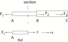
The top
figure below shows the case of axial loading of a rod ABC with external
forces F1, F2,
and F3 acting on the rod. If the
objective is to identify the internal force in the portion of the rod
between A and B, pass a section at an arbitrary location between A and B
and isolate that portion
of the rod. The bottom figure below
shows a free body diagram (fbd) of the isolated
portion of
the rod. From the fbd the “internal” force F must balance the applied
force, F1, for equilibrium
to be satisfied. The result is
that F =
F1.
This same methodology applies for cases of bending and torsion of
structural members.
|
Click
here to return to the introduction.
|