Pipeflow / Pumps / Turbines (continued)
|
Turbulent Flow
through single pipes (Start with the
energy equation.) In
general between sections of a pipe Energy
In + Net Work Rate = Energy Out + Loss Consider
sections one and two with two being downstream of one. Express this energy equation
in terms of head (ft or m).
Assume steady, viscous,
incompressible, uniform flow. P1/γ + V12/2g + z1 + net work rate in head loss = P2/γ + V22/2g + z2 + head loss or P1/γ + V12/2g + z1 + dW/dt)/Qγ = P2/γ + V22/2g + z2 + HL where P1 and P2 =
the static pressures at sections 1 and 2 (lb/ft2, N/m2) γ =
specific weight of fluid (lb/ft3 or N/m3) V1 and V2 =
the fluid velocities at sections 1 and 2 (ft/sec, m/sec) g =
acceleration of gravity (32.2
ft/sec2, 9.8 m/sec2) z1 and
z1 = elevations at stations 1 and 2 dW/dt = net work rate in (ftlb/sec, Nm/sec) + for pump and – for turbine Q
= flowrate (ft3/sec, m3/sec) Note:
Qγ =
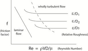
mass flowrate (slugs/sec, Kg/sec) HL = f
L/D (V2/2g) f
= friction factor; f depends on the Reynolds number and the relative
roughness of the pipe using the Moody Chart
(figure below) L
= length of pipe between
sections 1 and 2 (ft, m) D = diameter of the pipe (ft, m) V = fluid velocity in pipe between sections 1
and 2 (ft/sec, m/sec)
The Moody Diagram (below) Click
here to continue discussion. |
All rights reserved.