Shear and Bending Moment Diagrams


Key Concepts:   External loading on beams results in a distribution of shear force, V, and

bending moment, M, along the axis of the beam.   Diagrams showing this distribution help
identify critical sections in the beam where maximum shear and bending stress occur.


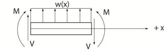
In a Nut Shell:  Use shear force and bending moment to calculate the shear stress and axial
(bending) stress at all sections along the beam. 
 The figure below shows the sign convention
for  positive values for
shear force, V, bending moment, M, and distributed loading, w(x).


The chart below lists the four common types of external loading.


            Concentrated Load     ( lb or N)


       Concentrated Moment    (ft lb or N m)


    Uniformly Distributed Load   (lb/ft or N/m)


      Variable Distributed Load   (lb/ft or N/m)


Calculation of Shear Force and Bending Moment Distribution


Two methods are available to determine shear force and bending moment distributions.  In the

direct method you simply draw free body diagrams at sections along the beam where you
wish to determine shear force and bending moment.  The second method uses relations between
shear and bending moment to construct the shear and bending moment diagrams.


                             Shear and Bending Moment Distribution


          Calculation using the

               Direct Method


           Calculation using

  Relations between Shear and

         Bending Moment


Return to Notes on Solid Mechanics

Copyright © 2019 Richard C. Coddington
All rights reserved.