|
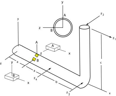
Example: The pipe assembly shown below
is subjected to four forces F1, F2, F3, and
F4.
Find the normal and shearing stresses for elements A and B at a section of
the pipe a
distance of 4 inches from the end. Element
A is at the top center-line of the pipe and
element B is on the outer surface along the
z-axis. Also plot the elements at both
locations showing the normal and shearing stresses on each face of the
element..
The following data
applies:
F1 = 150 lb,
F2 = 200 lb,
F3 = 50 lb, F4 =
150 lb a = 4 in, b
= 6 in, c
= 10 in.
x-sectional area of pipe =
0.8 in2 , Izz
= 0.3 in4, J
= 0.6 in4, Pipe OD = 1.9 in
Strategy: Construct
a free body diagram of the pipe assembly by cutting the pipe at a
section located distance a from the end of the pipe. Determine the axial force, bending moments,
shear force, and torque at that section.
Next calculate the axial stress using
P/A, and the bending stress using σ = Mc/I. You will
need to combine these stresses appropriately to obtain the total normal
stress. Also calculate
the shearing stress from torsion using Tc/J and the
shearing stress from transverse shear
using VQ/It. Combine these stresses to
get the total shearing stress. Show the combined
normal and shearing stresses on elements A and B.
Click
here to continue with this example.
|