Mohr’s
Circle - Stress
|
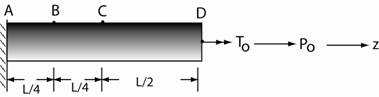
Example: An external torque, TO,
and external axial load, PO acts on the circular shaft, ABCD. Points B and C are at the
top of the shaft as shown below. Find
the maximum normal stress in the shaft at B and C. The radius of the shaft, c, is 2
inches. PO = 10 kips. TO = 10,000 lb in. |
|
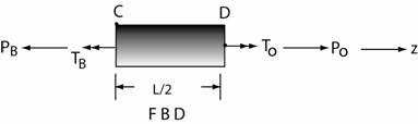
Strategy for point C: Construct
a FBD (free body diagram) to determine the internal torque and axial force at a section
of the shaft through C. Identify the
components of normal and shearing stress on the element at
C. Then construct Mohr’s Circle to
determine the principal stresses at C. The FBD of the shaft at
section C is as follows. → Σ Fz =
0 PO −
PC = 0
PC = PO →→ Σ Mz
= 0 TO −
TC = 0
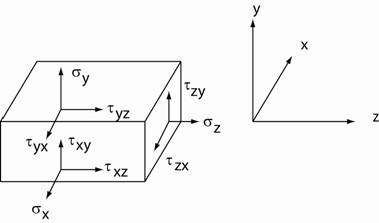
TC = TO Element at C: There are no forces acting
on the top face at point C in the shaft.
So all components of stress are zero. σy =
0. τyz =
0, τyx = 0. As a result: τzy =
0, τxy = 0 There is no axial load in the
x-direction so σx = 0. Click here to continue
with this example. |
| Return to Notes on Solid Mechanics |
|---|
All rights reserved.