Example - Analysis
of a Frame/Machine
|
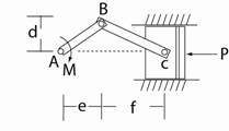
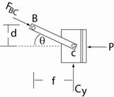
Note that the crank, AB, is a frame element since it supports bending due to the applied moment whereas the connecting rod, BC, is a two-force member (meaning a truss element). So the resultant force in the connecting rod acts along the member BC. The free body diagram (FBD #1) of the entire system (crank + connecting rod + pistion) is: With the Data: d = 50 mm, e = 75 mm, f = 175 mm, and M = 1.5 kNm. From equilibrium Σ MA = 0 M - Cy (e + f) = 0 so Cy = M / (e + f) Cy = 6.0 kN (result) The free body diagram (FBD #1) of the connecting rod + pistion is:
Now tan θ = d/f = 0.286 so θ = 15.945o and Σ Fy = 0 gives - FBC sin θ + 6 = 0 So FBC = 21.84 kN and Σ Fx = 0 gives 21.84 cos θ – P = 0 Or P = 21.84 cos θ giving the result as: P = 21.0 kN |
All rights reserved.