Analysis
of Gear Trains
|
In a Nutshell: The basic equations
governing shear stresses and angles of twist are the same for single shafts
with single or multiple applied torques, for single shafts with different diameters along
the shaft, for single shafts with changes in material along the shaft, for different
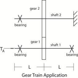
combinations of shaft size, location of applied torque, etc, and for multiple shafts connected
by one or more gears leading to the term gear trains. The table below lists the two
basic equations governing shafts subjected to applied torques.
where τ
= shearing stress - (MPa), (N/mm2), (lb/ft2), (lb/in2) T = applied torque - (N m),
(N mm), (lb ft), (lb in) c = radius of the shaft - (m), (mm), (ft), (in) J =
polar moment of inertia of area of the shaft (circular shafts only) Units for J - mm4, m4, in4, ft4 φ =
angle of twist in radians L =
length of the shaft - m, mm, ft, in G = shearing modulus of elasticity - (GPa), (Mpa), (lb/ft2), (lb/in2) . |
||||
|
Strategy: Both shear stress
developed in one or more shafts and angle of twist in one or more shafts are directly
related to torque. Thus, as a first
step, one needs to determine the torque developed in each
shaft by passing sections in the shafts, constructing free body diagrams, applying the equations
of equilibrium, and recognizing that the force on one gear tooth is the same on
the mating gear tooth. |
||||
|
|
| Return to Notes on Solid Mechanics |
|---|
Copyright © 2019 Richard C. Coddington
All rights reserved.