Analysis of Centrifugal
Pumps
|
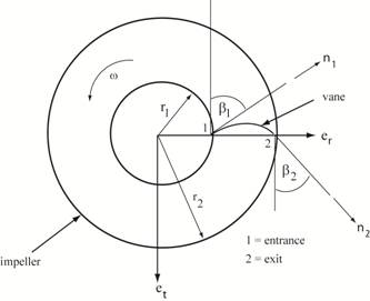
Velocities at entrance (1) and
exit (2) of vane on impeller: V =
U + W
where V =
the absolute fluid velocity measured in the inertial frame of
reference U = the velocity of the vane rotating about the z-axis W =
the velocity of the fluid relative to the vane where er = unit vector in radial direction, et
= unit vector in tangential direction n1= unit vector along vane at the entrance (attached
to vane) n2 = unit vector along vane at the exit (attached to
vane) ω = absolute angular
speed of impeller r1 = radius at
entrance section of vane, r2
= radius at exit section of vane β1 = angle of vane at entrance, β2 = angle of vane at exit At entrance 1: At exit 2: U1
= ˗
r1 ω et
U2
= ˗ r2 ω et
W1
= w1 n1
W2 = w2 n2
V1
= ˗
r1 ω et + w1 n1
V2
= ˗ r2 ω et
+
w2 n2 V1
= r1
ω et + w1 ( er sin β1
˗ et cos β1)
V2
= r2 ω et
+
w2 ( er
cos β1 + et sin β1) V1
= (
˗r1 ω ˗ w1
cos β1 ) et + w1 (sin β1 ) er V2
= (˗ r2 ω + w2
sin β1) et + w2 (cos β1
) er Click
here for a display of the vector diagrams. |
Copyright © 2019 Richard C. Coddington
All rights reserved.