Analysis of Centrifugal Pumps (continued)
|
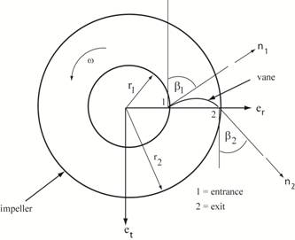
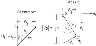
Vector diagram of velocities at
entrance (1) and exit (2) of vane on impeller: V
= U + W where | U1 | = r1
ω and | U2 | = r2
ω Note: The relative velocity diagrams are
essential in the analysis of fluid motion on the impeller since
the transverse components of the absolute fluid velocity, Vt1 and
Vt2 , need to be
calculated. Note: Vt1 = 0
and |V1| = Vr1 for a centrifugal pump at the entrance,
station 1 Click
here to return to discussion of centrifugal pumps. |
Copyright © 2019 Richard C. Coddington
All rights reserved.