Transformation of
Stresses/Mohr’s Circle
|
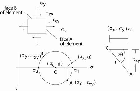
Construction of Mohr’s Circle starts with identifying “faces” on the element. Each face of the element corresponds to a point on Mohr’s Circle. See the figure below. A = a point on Mohr’s circle corresponding to “face A” on the element B = a point on Mohr’s circle corresponding to “face B” on the element C = center of the circle with coordinates ( σc , 0 ) Steps to Plot
Mohr’s Circle
Sign convention on Mohr’s circle: + normal stresses indicate tension and - normal stresses indicate compression + shearing stresses are counterclockwise (CCW) and – shearing stresses are (CW) Important points to
note regarding Mohr’s Circle
both in the same direction.
where σ1 and σ2 are the principal stresses |
| Return to Notes on Solid Mechanics |
|---|
All rights reserved.