Shear and Bending Moment Diagrams


Key Concept:  The distribution of shear force and bending moment along the axis of a beam

is important in determining the load capacity of a beam.


In a Nut Shell: 

A frame element (or beam element) is a structural member that resists both shear and bending due to applied loads.  A common example of a frame element is an I-beam.


The shear force is commonly represented by the symbol V.  The bending moment is

commonly represented by the symbol M.  The distributions are  V(x) and M(x).


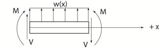
Strategy to find the shear and bending moment distribution along a beam.

                                       (Detailed in the table below)


Start by drawing a FBD of the entire beam to determine the support reactions.  This
step is usually needed.  Note that pin and roller supports cannot support moments.

Method 1   to calculate the shear and bending moment along the beam

Pass sections along the beam where distributed loads, concentrated loads and/or concentrated moments occur in order to calculate the shear and

bending moment in each section by summing forces and summing moments about the end point of the section.


Method 2  to calculate the shear and bending moment along the beam

Use  dV/dx =  w(x)  and  dM/dx  =  V(x)   and integrate.


where   w(x) is the distributed loading along the beam (lb/ft, N/m)

            M(x) is the bending moment at section  x  (ft lb, N m)

            V(x) is the shear forces at section  x  (lb, N)


The positive sign convention is as follows:


Click here to continue with Method 1.          Click here to skip to Method 2.


   Return to Notes on Dynamics


Copyright © 2019 Richard C. Coddington
All rights reserved.