Shear
and Bending Moment Diagrams using Relations between Shear
and
Bending Moment
|
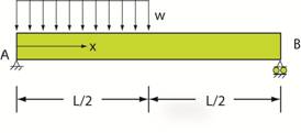
*Example: The beam AB shown below is simply supported
at A and by a roller at B. A uniformly distributed load, w, acts on the first
half of the beam. Plot the shear and bending moment diagrams showing the distribution
of shear and bending moment along the axis of the beam. Strategy: Use relations among shear and bending
moment to expedite solution. Click here for a reminder of this method. The FBD of the entire beam (where the equipollent
load wL/2 acting L/4 from A replaces the distributed load, w) is: From equilibrium:
→ ΣFx = 0
Ax
= 0 CCW
ΣMA = 0 By
L – (wL/2)(L/4) = 0 By
= (wL/8) ↑
ΣFy = 0 Ay –
wL/2 + wL/8 = 0 Ay
= 3wL/8 Solution: The shear
force at x = 0 is 3wL/8 and the slope
is dV/dx = ˗ w. So the shear
force |

| Return to Notes on Solid Mechanics |
|---|
All rights reserved.