Bending
Members (Beams)
|
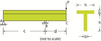
*Example: Find the maximum bending
stress (tensile) and minimum bending stress (compression) at section
above B in the overhanging beam shown below.
The beam is supported by a smooth
pin at A and a roller at B. The following data apply: c = 4 m, d = 2 m, h = 80 mm, b = 20 mm, and P = 5000 N |
|
Strategy: Apply the bending stress
relation σ = Mc/I where M is
the bending moment at the section, c is the
distance to the outer fiber, and I is the moment of inertia of area about the centroid
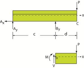
(neutral axis) of the section. Use a
free body diagram to determine the bending moment, M. The support reactions at A
and B can be determined from equilibrium using the top free from equilibrium by the
bottom free body diagram. So proceed
with the bottom FBD. CCW ΣMz
= 0 − M
− Pd = 0 and for the data: M = −
(5000)(2) = − 10000 N mm Since P bends the beam “downward” at end C, the
“top fibers” of the beam will be in tension and the “bottom
fibers” will be in compression.
The c will be the distance from the neutral axis of the
entire X-section to either the top or bottom fibers of the beam. Click here to continue
with this example. |
Copyright © 2019 Richard C. Coddington
All rights reserved.